This page describes the electronics of the train controller. It is built around a Raspberry Pi 2B and two custom circuit boards that connect it to the motor, the sensors and the track.
The two circuit boards
The two boards plug onto the Raspberry Pi like “hats”.
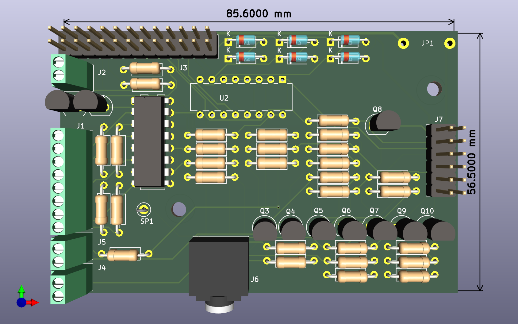
The Bottom Hat converts the Raspberry Pi’s 3.3 V signals to 5 V with BC337 transistors. It also carries the overcurrent protection and the current measurement (see below).
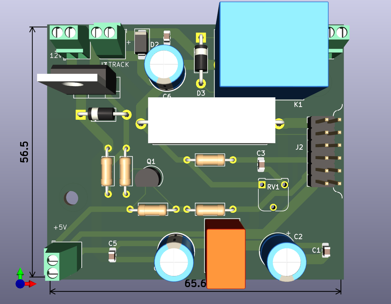
The Top Hat holds the 12 V circuitry. It converts the 5 V signal to 12 V and drives an IRF4905 P-channel MOSFET, which feeds the motor directly. A switching regulator on this board makes 5 V from the 12 V supply, and a relay powers one of the two tracks.
Controlling the motor speed
The speed is set with PWM (pulse-width modulation) from a hardware PWM pin of the Raspberry Pi (GPIO 18). A 100 kΩ pull-down resistor keeps that pin low while the Raspberry Pi starts up, so a train cannot move by accident.
The motor starts turning only when it receives about a third of the full voltage, roughly 4 V on the 12 V supply. The slowest running speed is therefore set just above that point. The controller uses a PWM frequency of 100 Hz for slow running and 5,000 Hz for normal speed.
Protection
Overcurrent protection is built entirely in hardware. A latch circuit on the Bottom Hat watches the current through a small shunt resistor. If the current gets too high (the trigger level is set with a trimmer), the circuit pulls the PWM signal to ground and the motor stops. This works independently of the software. In addition, an MCP3008 converter measures the motor current, and the dashboard shows the peak and effective values.
Sensors, track and train identification
- IR dots (infrared sensors) detect the slow-down zone and the stopping points at Platform A and Platform B. Reed contacts, switched by magnets under the train, were tried earlier but did not work: the magnets were too thick to stay attached, and thinner ones are not available.
- A stepper-driven (or relay-driven) turnout routes the train to one of the two platforms.
- A scanner identifies each train by a code on a sticker under the train. The scanner can read both barcodes and QR codes, and I am still testing which works best. There is little space between the wheels of the train, so the code has to be small.
Circuit diagrams
The full circuit diagrams of both boards are available as PDF files. They stay sharp when you zoom in.
- Bottom Hat schematic (PDF): the circuit diagram of the Bottom Hat, with level shifting, the overcurrent latch and the current measurement.
- Top_HAT_Schematic: the circuit diagram of the Top Hat, with the motor driver, the 5 V regulator and the track relay.